Using this convention, we can construct a state table looks like the following:
        Present External |  Next    External
         State   Inputs  |  State   Outputs
        ------------------------------------
         S1  S0    X      |  D1 D0      Y
        ------------------------------------
         0   0     0     |  0   0      0
         0   0     1     |  0   1      0
         0   1     0     |  1   0      1
         0   1     1     |  1   1      1
         1   0     0     |  0   0      1
         1   0     1     |  0   1      1
         1   1     0     |  1   0      0
         1   1     1     |  1   1      0
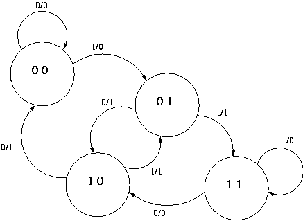
The first two rows of this table would be interpreted as follows: "If
the present state is 00, the output is zero. If the external input
during state 00 is 0, the next state will be 00 again, but if the
external input is 1, the next state will be 01." The next two rows would
be interpeted to say, "If the present state is 01, the external output
is 1. If the external input is 0, the next state will be 10, but if it
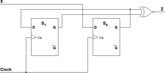
is 1, the next state will be 11.We could minimize the three functions on the right side of the state table using Karnaugh Maps, but D1 can be seen to be equal to S0 by inspection, saving a bit of work. Likewise, D0 can be seen by inspection to be the same as X. Finally, we can also see by inspection that Z is true if and only if S1 is different from S0, that is Z = S1 xor S0. Thus, the following circuit implements the entire state machine: